
Introduction
Because flanges allow the assembly and maintenance of system components without the need for cutting and welding pipe, they play an important role in piping systems. However, the structural integrity and leak tightness of waterworks piping systems are only as strong as the weakest element, which often is the flange connection between various valves and fittings. Yet because piping systems are subject to many types of loads and are constructed of a variety of materials, understanding and predicting the rating and performance of those flange connections is difficult. This is further complicated by the fact that different sealing mechanisms such as gaskets, O-rings and mechanical seals can significantly affect the performance of the connections. As far as ratings, ASME B16.1 lists pressure ratings for Class 125 flanges from 50 to 200 psig depending on size, material and temperature.
THE GEOMETRY OF FLANGES

Figure 1. Typical waterworks flange connection
A basic flange found on most waterworks valves and fittings is shown in Figure 1. The connection consists of a circular ring or flange welded to or cast integrally with the valve body and pipe. The basic dimensions of a flange consist of the outside diameter (OD), bolt circle diameter (BC), thickness (T) and the number and size of the bolt holes. The bolt pattern in valves and fittings typically straddles the vertical centerline. The flanges of two fittings mate together and are sealed with a resilient gasket, which is tightly compressed by the bolts located in a circle concentric with the pipe OD. To obtain a tight seal, the bolts must withstand the hydrostatic and force of the pipe and compress the gasket to a multiple of the maximum pressure of the system.
 Figure 2. 24 NPS plug valve flange with eight tapped flange holes
Because of the body shape of some valves, valve flanges often contain tapped holes instead of through holes, which affects the selection of bolting. The 24 nominal pipe size (NPS) eccentric plug valve shown in Figure 2 requires four tapped holes on the top and four tapped holes on the bottom of the flange because the nuts behind the flange would interfere with the main part of the valve body.
A flange is a structural element of the piping system that must withstand the pressure and pipe loads related to that system since the element is a rigid or restrained joint. The flange connection will not slip or pivot, and it must withstand the internal pressure forces without any external restraint. Certain push-on and mechanical joint connections often used below ground are not restrained. This is an important distinction that affects the supports, anchors and thrust blocks needed for many systems. The flange must be strong enough to transfer pipe loads, pressure forces and gasket loads from the bolts to the connecting pipe, fitting or valve. When a pipe is pressurized internally, the hydrostatic forces tend to stretch the pipe and pull the flanges apart. The bolts must maintain contact between the mating flanges and gaskets without excessive stretching.
 Figure 3. Examples of flange types
To absorb these loads, a designer has several types of flange shapes available as shown in Figure 3. The simplest is the ring flange, which consists of a flat plate of uniform thickness.
The hub flange is similar to the ring flange but has additional material at the base of the flange so loads are distributed more uniformly to the pipe or fitting. Ring and hub flanges can be attached to the pipe by welding or threading (companion flange). High-pressure steel flanges often have a raised face and sloped hub that optimizes the strength-to-weight ratio of the flange. These are attached to the pipe with a butt weld. The raised portion of the flange focuses the bolt load over a smaller gasket area, which improves the gasket’s performance. Finally, when the purpose of the flange is to block off the end of the pipe, a blind flange is used, which consists of a solid flat plate. A flat plate is an inefficient shape to withstand pressure (as opposed to dished heads, which are better), so blind flanges tend to be thicker than pipe flanges.
FLANGE MATERIALS
Pressure ratings of flanges are based on their material of construction. This makes sense because steel can be twice as strong as gray iron. However, to understand how material strength affects flange ratings, it is important to understand fundamental mechanical properties of metals.
 Figure 4. Gray iron magnified 400 times
 Figure 5. Ductile iron magnified 400 times
For example, the mechanical properties of gray iron and ductile iron differ greatly despite the fact they are both iron alloys. To produce a cast flanged fitting, pig or scrap iron is melted down and combined with other elements such as carbon and silicon to produce unique properties. Figure 4 shows that when gray iron solidifies, its grain structure includes graphite (carbon) in the form of flakes, which appear as jagged lines in this illustration. These flakes give gray iron its strength and hardness, but at the same time, make this metal brittle. Nevertheless, gray iron is used extensively in fittings and many other products including engine blocks because the graphite structure absorbs noise and exhibits favorable resistance to wear.
Conversely, when ductile iron is cast, the molten metal is treated with magnesium, which causes the graphite to solidify into the nodules seen in Figure 5. The nodule shape gives ductile iron greater strength and less brittleness than gray iron. Materials such as ductile iron tend to deflect significantly before they fracture. This tendency, which is similar to what happens with a rubber band, is called ductility. Granted, that rubber band may deflect five to 10 times its length before it breaks, but ductile iron can deflect as much as 18% before breaking. Since ductile iron can bend like steel, it also has the ability to absorb shocks, which helps reduce line breaks in water main applications. This shows how knowledge of materials and their mechanical properties allows engineers to establish safe and predictable flange designs for use in various industries.
FLANGE STANDARDS
To allow components within an industry to be interchangeable, engineers have developed standard dimensions over many decades for bolts and flanges for a variety of pipe sizes and pressure ranges. The first such effort was undertaken by the American Society of Mechanical Engineers (ASME). ASME is dedicated to ensuring the safety of the general public from the risks of pressurized systems such as boiler piping. Beginning in 1920, the ASME B16 committee assumed responsibility for developing codes and standards related to valves, pipe flanges and fittings. The committee’s published body of work includes standard dimensions and pressure/temperature ratings for gray iron flanges and fittings (ASME B16.1), ductile iron (ASME B16.42) and steel (ASME B16.5). ASME also recently produced a standard for large steel flanges (ASME B16.47), but it is mainly used by the petroleum industry. Compliance with these standards is voluntary, but their application ensures safety at stated pressures and temperatures as well as uniformity so that flanged valves and fittings from different manufacturers can be interchanged.
Similarly, the American Water Works Association (AWWA) A21 Committee publishes flange and fitting standards that mate with some of the ASME flanges, but are designed for cold water service. Most notably, AWWA C110 ductile iron and gray iron fittings describes 3- to 48-inch fittings and flanged joints with Class 125 dimensions for waterworks service. These fittings and their ratings are based on extensive burst testing and provide a safety factor of at least three times the rated cold working pressure (AWWA C110). Because the products are intended for cold water, the ratings of AWWA fittings and flanges are higher than a similar ASME fitting. Keep in mind, however, that the ASME fittings are also used for steam service, which is far more hazardous than waterworks service.
It is also important to realize that while valves incorporate these flanges, their pressure ratings may differ based on different valve standards. For example, some butterfly valves with Class 125 flanges have flanges capable of 250 psig, but AWWA C504 rubber-seated butterfly valves limits the maximum working pressure of gray iron valves to 150 psig.
FLANGE CLASSES
ASME and AWWA standards provide dimensions for various classes of flanges. Given those dimensions, the standards development organizations establish pressure ratings for flanges and fittings based on the materials from which they’re made and the temperatures at which they’re used. These pressure classes of 125, 250, 300, etc. cause considerable confusion in the industry. This is because the classes often are interpreted as rated pressures for the flange; but nothing could be further from the truth.
Instead, these classes are “designations” that generally represent a pressure and temperature for saturated steam. For example, an ASME B16.1 Class 125 flange is rated for 125 psig at 353ºF (178ºC), which is the boiling temperature for water at that pressure. As temperature increases, the pressure rating of the flange decreases. For example, a Class 150 flange is rated about 270 psig at ambient conditions (i.e. 100°F or 38ºC), 180 psig at 400°F (204ºC), 150 psig at 600°F (316ºC), and 75 psig at 800°F (427ºC). At ambient temperatures, it makes sense that the pressure ratings are higher than the saturated steam pressure. When the temperature rises, the rated pressure goes down and vice versa. Pressure and temperature tables in the applicable standards must be consulted to apply them to a piping system.
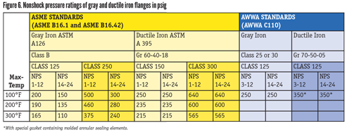
A general summary of flange pressure ratings versus temperatures is shown in Figure 6. The ASME pressures represent nonshock pressure ratings, as in steady pressures, not pressure spikes or cyclic water hammers. Conversely, AWWA fittings are adequate for the rated pressure plus a surge allowance of 100 psi or half the rated working pressure, whichever is less (AWWA C110). The table brings to light some important observations.
- In all cases, as the maximum temperature increases, the pressure rating of the flange goes down. Metals are weaker at high temperatures.
- Most of the time, the pressure ratings do not match the class designation at 100°F (38ºC).
- As the class designation increases, the pressure rating increases.
- Ductile iron flanges are rated higher than gray iron flanges.
- AWWA C110 only specifies Class 125 drilling.
- The AWWA fittings are not rated for high temperatures.
The ASME standards contain many other standard pressure classes. But in the waterworks industry, Class 125 and Class 250 apply to gray iron flanges, while Class 150 and Class 300 apply to ductile iron, steel and stainless steel (ASME B16.1, ASME B16.42). The bolting patterns of Class 125 and Class 150 match, as do Class 250 and Class 300. It is important not to mix the rating of the fitting with the drilling of the flange. Most AWWA fittings have Class 125 drilling, but a 250 psi rating even when made of gray iron (AWWA C110).
In the waterworks industry, AWWA publishes standards for flanged fittings and valves that are related to the ASME standards. Because AWWA fittings and valves are used with water, which is considered a safer medium, the general safety factor may be lower than with the more hazardous high-temperature steam applications. AWWA also allows several alternate grades of gray iron and ductile iron.
FLANGE SIZES
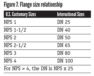
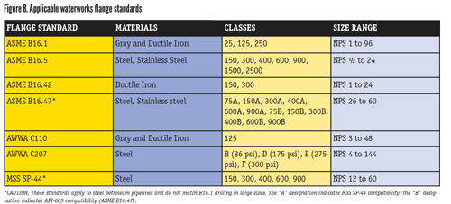
Even though every flange size and pressure class has an exact OD, flange sizes are denoted by the size of the pipe, which is expressed as NPS. It is often assumed that NPS stands for the size in inches of a pipe; but technically, the NPS value is a dimensionless number related to the reference nominal diameter (DN) used in international standards. Similarly, the DN sizes are dimensionless and not millimeters. The general relationship is shown in Figure 7 (ASME B16.5). Each flange standard has limited size ranges and pressure classes. Figure 8 presents the scopes of the various standards. In addition to those listed, flange standards exist for stainless steel, copper and international (metric) drilling. Still, these standards are the most common in this industry.
Some general facts should be understood when using these standards.
First, Class 125, Class 150 and AWWA Classes B, D and E flanges have the same bolt pattern and can be joined together (AWWA C207). The same goes for Class 250, 300 and AWWA Class F.
The steel flanges given in ASME B16.5 only go up to NPS 24; so that standard is of little use for large flanges. Because of this, AWWA C207 is used for large steel flanges in the waterworks industry. C207 is a relatively new standard for which dimensions for sizes up to NPS 144 in 1978 (AWWA C207) were just released. Therefore, many valves and fittings in the field have special flange drilling. Caution should be exercised when fabricating replacement equipment for existing piping systems.
Class 125/150 drilling is the most common flange in the waterworks industry. In fact, it is so common some projects specify iron valves with 250/300 flanges drilled specially to mate with a Class 125/150 bolt pattern. This is done so that the valve can carry the same pressure rating as the steel mating flange. However, doing so is not practical since it adds unnecessary weight to the valve and is unsightly when the flange diameters do not match in the pipeline. A better practice is to specify a Class 125/150 valve flange in ductile iron, which will carry a pressure rating similar to the steel mounting flange.
Finally, Class 250/300 drilling is common, but only available up to size NPS 48. Above that size, flanges will have the 125/150 drilling with the pressure rating dependent on the material (ASME B16.1).
CONCLUSION
Flanges are an important component of piping systems and are provided by both valve and pipe manufacturers in many configurations. Complete knowledge of their design and applicable standards is essential for a piping system to be successful. In the waterworks industry, valve and pipe flanges are provided in many alternate materials and conflicting pressure class designations. To avoid serious construction problems and unneeded costs requires thorough knowledge of flange ratings and specification of flange systems that meet the required pressure and temperature requirements of the piping system.